User's guide for Smart Spot Starter Kit
Introduction
In order to offer a simple and intuitive way to get started with our Smart Spot we have developed an Open Source solution called Smart Spot Starter Kit, which has an obvious educational purpose. Just by simply obtaining this kit and follow this guide you will be able to manage the device and to acquire data from its board sensors, apart from the ones you connect with your smartphone.
To achieve this, we take advantage from technologies like Physical Web. Users interact via their smartphones thanks to our device that sends "push" notifications with digital content through Bluetooth without the need to install native Apps.
In order to monitorize the air pollution, Smart Spot measures the NO2, CO, SO2 and O3 at specific points in real time. We have a sophisticated high precision lab, with a Mass Flow Controller and a Zero Air Generator, where through Machine Learning algorithms we improve the precision of our sensor measures reducing the effect of cross sensitivity.
For the care and management of data collected by the Smart Spot a maintenance platform is needed, our device can be managed remotely by platforms which use OMA LWM2M as FIWARE. We deploy FIWARE to manage Smart Spot data and also, we integrate our solution in already existing FIWARE ecosystems.
Optionally, this system provides information about crowds in specific areas, detecting people with smartphone WiFi switched-on.
What do you need?
What is included with The Smart Spot Starter Kit:
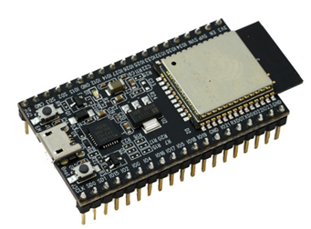
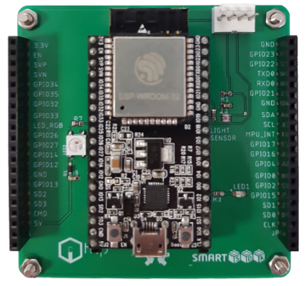
- ESP32 DevKitC:
- Starter Kit firmware
- Physical Web
- Crowd Monitoring
- LwM2M server
- Integration with I2C sensor
- GPIO driver
- Expansion Board:
- Temperature, Humidity and Pressure Sensor.
- Accelerometer and Gyroscope.
- Luminosity Sensor
- RGB led
- GPIO Led
- Micro USB Cable
- Smart Spot Air Quality Expansion Board
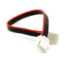
- I2C Cable (included with the expansion board)
-
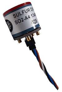
4 x Gas Sensors:
- Sulfur Dioxide (Red).
- Ozone + Nitrogen Dioxide (Yellow).
- Carbon Monoxide (Green).
- Nitrogen Dioxide (Orange).
Getting Started
Device Configuration
This chapter is a guide for Windows users. In case you use another OS, you can find further information in the following link: ESP-IDF
-
First, you need to download the ESP32 toolchain by clicking in this link: ESP32 toolchain. Unzip it and place somewhere safe. This guide assumes the environment is placed in C:\ .
-
You will also need the ESP32 API. In order to download it, open a terminal, navigate to a directory where you want to place the IDF and use these commands:
``` $ git clone --recursive https://github.com/espressif/esp-idf.git
$ git checkout tags/v3.0-rc1
$ git submodule update –init ```
Every time you restart your PC you will need to define the IDF\ _PATH by using this command:
$ export IDF\_PATH="C:/msys32/home/user-name/esp/esp-idf"In case you want to set the path permanently, check out this link: https://bit.ly/2KxiunW
-
Now is time to download the Smart Sport Firmware. You should open a terminal in another directory and clone our firmware by using the following command:
$ git clone –-https://github.com/HOP-Ubiquitous/SmartSpot\_SmartSDK\_Firmware.git -
Once you downloaded everything, open the ESP32 toolchain in order to flash the firmware. Go to the directory where you placed the toolchain and execute the file mingw32.
 -
Plug your ESP32 into your PC. Then go to Device Manager and look for its port number (i.e.: COM3).
You may have to download its driver in case you are not able to flash. Download it here.
[USB to UART Bridge](https://bit.ly/2v0gwnS) -
It is time to flash the esp32. Open a Mingw32 terminal and copy the port and the directory of bootloader.bin, smartspot-esp32.bin, partitions_singleapp.bin and esptool.py:
- esptool.py directory
- Port
- Bootloader.bin directory
- smartspot-esp32.bin directory
- partitions_singleapp.bin directory
Replace them by the bolded words of the following command:
$ python
  /c/Users/HOPU/GitHub/esp-idf/components/esptool_py/esptool/esptool.py
  --chip esp32 --port COMX --baud 115200 --before default_reset --after
  hard_reset write_flash -z --flash_mode dio --flash_freq 40m --flash_size
  detect 0x1000
  C:/Users/HOPU/GitHub/SmartSpot_SmartSDK_Firmware/bootloader.bin 0x10000
  C:/Users/HOPU/GitHub/SmartSpot_SmartSDK_Firmware/smartspot-esp32.bin
  0x8000
  C:/Users/HOPU/GitHub/SmartSpot_SmartSDK_Firmware/partitions_singleapp.bin
Copy then the whole command and use it for flashsing the esp32.
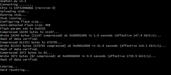
A message like the one above should appear if you flashed the firmware successfully.
Expansion board integration
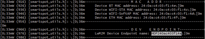
In case you don’t know the endpoint of the device you can use this command in order to use the log of the serial port (remember to use your port configuration):
$ miniterm.py COMX 115200
The endpoint will look similar to this:
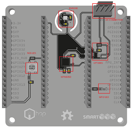
This is a detailed list of the expansion board components:
-
Bme280 : This well-known sensor from Bosch measures humidity with ±3% accuracy, barometric pressure with ±1 hPa absolute accuracy, and temperature with ±1.0°C accuracy. It can be used either with SPI or I2C.
-
Mpu6050 : this sensor contains a MEMS accelerometer and a MEMS gyro in a single chip. It is very accurate, as it contains 16-bits analog to digital conversion hardware for each channel. Therefor it captures the x, y, and z channel at the same time. The sensor uses the I2C-bus interface.
-
Opt3001 : is a sensor that measures the intensity of visible light. The spectral response of the sensor tightly matches the photopic response of the human eye and includes significant infrared rejection.
-
WS2812 : is an intelligent control LED light source that the control circuit and RGB chip are integrated in a package of 5050 components. It internally includes digital port latch and reshaping amplification drive circuit. Each color has a different meaning, representing the current status of the Smart Spot:
- Purple: Starting software.
- Blue: Attaching to global connectivity.
- Orange: Bootstrapping. Connecting to LwM2M servers.
- Green: Device fully functional.
- GPIO Led : is just simply a Led controlled by a GPIO pin of the ESP32. You can manage and switch it on/off from the dashboard.
The expansion board is completely plug and play. If you previously flashed the ESP32 correctly you will only have to plug it in its mark.
Gas Sensor Integration
The idea is to connect the Smart Spot Starter Kit with the gas sensors. Between the available gases, we selected the most important to quantify the air quality (gases required by the OMS), the most interesting depending of the use cases but also interesting gases to carry out corrections in measures:
-
NO2: Nitrogen dioxide (instance 0)
-
O3: Ozone (instance 1)
-
CO: Carbon monoxide (instance 2)
-
SO2: Sulfur dioxide (instance 3)
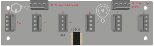
In order to carry out the connection between the Expansion board and the Smart Spot Air Quality Expansion Board you only have to plug the I2C cable to one of the two I2C Smart Spot Connectors. Regarding I2C Gas connectors, the every port must match its gas:
| Port | Gas |
|---|---|
| J3 | NO2 |
| J4 | O3 |
| J5 | CO |
| J6 | SO2 |
| J7 | Work in Progress |
| J8 | Work in Progress |
The Smart Spot LwM2M Client offers both a proprietary OMA LwM2M object called "SmartSpot Gas Concentration" created specifically to provide information related to interesting variables of the gas sensors, and on the other hand the standard IPSO Alliance Concentration Object. Information and specification about this last one can be found in this link.
These object are multinstance. Each analyte (the gas that is going to be measured) has a ID instance. For example, if you want to know the current concentration value of CO you will have to read the resource 3325/2/5700.
Device Deployment
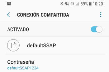
The Smart Spots have a pre-configured WiFi Station where devices will connect. This AP can be easily deployed from smartphones, GSM routers, common WiFi Access Points, …
The default configuration is: SSID name: defaultSSAP Password: defaultSSAP1234
You must create an access point in your smartphone (HotSpot) or router with the default SSID name and Password for the device to connect to the network. When this access point is created the device connect automatically.
With a Wi-Fi hotspot, you can share your mobile data connection on your smartphone wirelessly. Look in your Settings menu for Wireless & Network and check where you can enable a Wi-Fi hotspot. You should change now the SSID and Password for the ones above.
Infrastructure Deploy
In order to facilitate the interaction and configuration between user and devices, a fiware infrastructure will be deployed. It will allow the connection and configuration of LwM2M clients, storing data and building custom applications. (If you have any LwM2M Server were to connect your devices you can skip this section).
Prerequisites
Configuration
Services in the architecture are deployed using a docker-compose file, all the documentation and code can be found here.
The repository can be easily cloned with the following command:
$ git clone https://github.com/HOP-Ubiquitous/fiware-docker-infrastructure
Ubuntu User
Therefore, the configuration options are explicitly declared in this file. For services with complex configuration a brief extra description is provided.
Please, take into account that the guidelines that you can find in the HOP Ubiquitous github are thought for a localhost deployment. If you are making a distributed deployment, please make sure to have the proper ports open and the different hosts with visible ips addresses between each other.
Windows User
For Windows users is necessary install a virtual machine to run Ubuntu in your PC. VirtualBox is a option for this issue. Create a new virtual Machine, choose a name, type Linux and Version Ubuntu (32bits or 64bits). Select the options that you prefer of your virtual machine in the next dialog windows.
The first time that you start your virtual machine, VirtualBox will ask you about the Ubuntu Install file. Search the file in this window dialog and Ubuntu will start to install.
For a correct operation of Smart Spot Open Hardware you must consider that the network adapter is “bridge adapter mode”. This option is in VirtualBox / configuration / network, and the dropdown “connect to” and choose “Bridge adapter”.
Deployed services
IoT Agent Configuration
In order to be able to map the OMA LwM2M information model to OMA NGSI entities, attributes and metadata a configuration file is created reflecting the correspondence. config.js in the docker-compose/ directory contains two blocks:
-
LwM2M Server configuration, specifying aspects like server port, content- format used or the log level of the service.
-
NGSI configuration, where information about the http server, the storage and the mapping between the protocols are specified. On the other hand, a dynamic configuration can be carried out using the service API. The postman collection of this service provides a skeleton template.
More information about the component can be found in the LwM2M IoT Agent Guide.
Cygnus configuration
agent.conf In order to configure the channels and databases in which the information will persist, it is necessary to configure the agent.conf file in the docker-compose/ directory. This file will be loaded into the docker container as a configuration file. An example of the file that is loaded by default can be found in this url. In the previous example we can see how to initialize each of the different connectors to databases.
To simplify the debug better add only the necessary onesOrion-Cygnus Communication In order to get the information that reaches Orion to be persistent, it is necessary to create subscriptions on Orion by setting Cygnus as the url of the callback. An example of the subscription to create can be found in the postman collection within the main directory. More information about the component can be found in the Cygnus Guide.
QuantumLeap, Crate and Grafana configuration
These three components work jointly to accomplish a visual representation of the information in Orion Context Broker. QuantumLeap is a library that receives Orion information through subscriptions and stores the information in a Crate database. Last, the grafana container launches a web services with user interface in which the Crate database deployed can be configured as data source. A more detailed guide of this services interaction can be found in the use-cases/ directory.
Perseo-core and Perseo-fe configuration
Perseo CEP is a Complex Event Processing (CEP) module. In this module, Perseo- core is the back-end of Perseo CEP, the rule-engine. It checks incoming events and, if any action must be done, it call to Perseo-fe through a POST request. Perseo-fe refresh the set of Perseo-core rule periodically. When Perseo-core send an action to Perseo-fe, it is responsible of send an action vía SMS, e-mail or HTTP. A more detailed guide of this services interaction can be found in the use-cases/ directory.docker-compose.yml In order for Perseo CEP can send a notification, it must have configured the following servers: SMPP, SMTP and HTTP in docker-compose.yml file contained in the docker-compose/ directory. The environment variables available for Perseo configuration can be found in this url.
Build, deploy and run
The architecture building and execution must contains using docker- compose must contains a previous step, the IoT Agent container building. This is due to the LWM2M IoT Agent madurity state. Currently some modifications in its code are needed and, for this reason, the modified source code is provided to ensure the interoperability between devices and Orion.
Build LWM2M IoT Agent
Within the IoT Agent folder execute:
$ docker build -t "iotagent:latest" $(pwd)
In order for the iotagent to receive its configuration, a config.js file must exist in the docker-compose directory (fiware-docker-infrastructure/docker- compose/config.js). This directory will include the information that must be mapped between the devices and the orion. In this section we are going to give an overview of those sections and explain how to configure them:
-
`config.lwm2m`: This section is about the Lwm2m server that we are setting up, the port in which LwM2M requests are going to be received, the default device type and the used protocols
-
`config.ngsi`: In this section the configuration about the services and devices that are going to interact with the LwM2M IOT-Agent is needed:
- `ContextBroker`: The host ip and the port of the Orion Context Broker need to be fixed here.
- `server`: Modify the server port only if you want it to be running in a different one, the default port is 4042. This same port needs to be setted as well in the providerURL (with the proper ip address).
- `deviceRegistry`: The database type that is going to be used to store the device registrations, it should be a mongodb instance.
- `mongodb`: The MongoDB ip, port and database name.
- `types`: This is one of the most important sections. In this section the
device type resource mapping is going to be specified. There are a set
of sections that can be left as default, but no the following ones:
- `lazy`: In this section we specify the lazy LwM2M resources that we want to be read. Name and type need to be fixed for each one.
- `active`: Same like in lazy section bus this time for active resources. The IOT-Agent will set a observer in every active resource after the device connection.
- `lwm2mResourceMapping`: This section is the one that is going to set the needed OMA-LwM2M resources to be read in order to map the lazy and active resources.
- `providerURL`: The URL in which one the LwM2M IOT-Agent API is going to be available. The specified port in the server section, needs to be the same here.
In this file you can find a config.js file as example for the FIWARE docker infrastructure that can be found in the HOP Ubiquitous gitHub. In the readme file of that repository, a complete guide to deploy the docker infrastructure can be found.
Build architecture through docker-compose
Please, take a look to the docker-compose.yml file, in this one you can find the port mapping between the host machine and the docker containers that are going to be deployed inside. Make sure that every port that is on the left side of the mapping is reachable. For example:
...

iotagent:

  image: iotagent

  ports:

    - "5693:5683/udp"
...
The 5693 port of the host machine (that is connected to the 5683 of the docker container) must be reachable from the network.
The following commands are docker commands, probably your current installation doesn’t allows you to execute those commands without root rights. In order to solve this issue you need to add your current user to the docker group. Make sure that the group exists and lather execute:
$ sudo gpasswd -a $USER docker
Now you are able to execute every docker command without root access:
First of all, in order to be able to execute docker-compose commands, you will need to go to the docker-compose directory. After that, you will be able to launch the infrastructure.
Launch infrastructure:
$ docker-compose up
Launch infrastructure in background:
$ docker-compose up -d
Stop infrastructure:
$ docker-compose down
Erase all stopped docker containers:
$ docker rm $(docker ps -a -q)
Initialize the device: Bootstrap
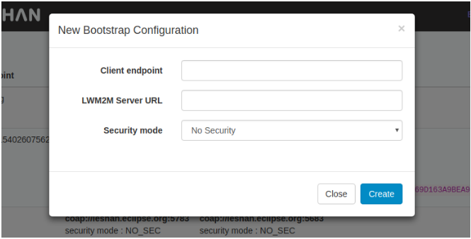
Every LwM2M device needs a previous tep that is called bootstrap. By this way, the device acquires the addresses of the LwM2M servers to connect with. To perform this step, in this guide we are going to use the Leshan Bootstrap server. Leshan is an open project source regarding LwM2M services by the Eclipse Foundation. They provide a good set of services including an online bootstrap server.
In the device that you have already acquired, leshan is already configured as bootstrap server. In the leshan website, you need to register your device filling the following data:
-
Client endpoint: Your device has an unique endpoint name (e.g HOP240ac403f14e).
-
LwM2M Server URL: For example “coap://iotAgentIP:ioTAgentPORT”. Please make sure that your device is connected to a network where the “iotAgentIP” is reachable, and internet too.
After this process, the device will be ready to be turned on, and perform the Bootstrap procedure.
Test the LwM2M deployment
-
When everything is running and the device is turned on, the communication between the device and the FIWARE services will start, we can test it sending some GET request to the ORION Context Broker, like the following ones:
- GET orion entities with a limit of 50: This requests retrieves the entit ies that the ORION Context Broker is storing with a limit of 50.
curl --header "fiware-service:SmartSpot" http://orionIP:orionPORT/v2/entities?limit=50- GET orion entities as data model: This requests performs same as the previous one, but the entities will be retrieved in the FIWARE datamodel format.
curl --header "fiware-service:SmartSpot" http://orionIP:orionPORT/v2/entities?options=keyValues&limit=50- GET types v2: Retrieves the types of the registered attributes in the fiware-service entity put as header.
curl --header "fiware-service:SmartSpot" http://orionIP:orionPORT/v2/types -
If every previous step has been performed properly, the requested information will be retrieved and the ORION API will be ready to be used in any kind of application.
-
For more information, the following links can be visited:
Compatibility and versions
The docker-compose service description do not use version tag in the majority of the services. That implies the use of the service last version at the time of perform the pull. There are some exceptions like the MongoDB version or the IoT Agent that must be build in the host machine.
To Be Done
Add FIWARE security stack Create different docker-composes adapting the components to the user case required. Change diagrams and add perseo documentation
Extensibility
From HOP Ubiquitous we are pretty interested in the extension of the services ready to be deployed. If you have experience with any other FIWARE component do not hesitate to contact us.
Maintainers
german@hopu.eu (FIWARE config)
joseluis@hopu.eu (FIWARE config)
felipe@hopu.eu (FIWARE config)
rafa@hopu.eu (Device configuration)
Known issues
Currently a IoT Agent memory issue has been discovered. The error implies the service stop and for this reason a restart condition is provided in the docker- compose file.