Creating your Air Quality Sensor with Cloudino
Introduction
This guide will help you to create your own air quality sensor unit using Cloudino, an IoT (Internet of Things) Agent, to remotely monitor your sensors and send your data to the FIWARE platform.
The Cloudino WiFi Connector can be used as a standalone device to directly communicate real-life objects to the internet or as an additional microcontroller dedicated to the network layer, working in parallel with actual microcontroller solutions like Arduino.
What you need to order
While using with Arduino, the Cloudino WiFi Connector works as another processor in parallel dedicated only to the network layer including the IoT protocols, leaving the Arduino dedicated to connectivity with sensors and actuators and allowing reprogramming Arduino via WiFi or Cloud.
In this manner, we can connect any sensor compatible with Arduino and process our data through the Cloudino and FIWARE platforms.
For the purpose of this guide we will use the following components to develop our air quality sensor unit:
- Cloudino WiFi Connector (CWC).
- Arduino UNO.
- PPD42NS. PM10 Sensor.
- DHT11. Temperature / Humidity Sensor.
- MQ-131. Ozone Sensor.
- Grove Multichannel. Gas Sensor (NO2, CO).
You can find the components in your local electronic shop or online in several places:
- https://www.robotshop.com/
- https://www.seeedstudio.com/
- https://www.sainsmart.com/
- https://store.arduino.cc/usa/arduino-uno-rev3
- https://www.sparkfun.com/products/13678
The Cloudino can be acquired directly by contacting the developer javier.solis@infotec.mx, victor.hernandez@infotec.mx or you can even build your own Cloudino device by using a ESP8266 and following the instructions from the Cloudino documentation.
How to add Air Quality sensors
Fig. 1 shows the schematic model for an air quality unit where the Arduino UNO Board connects 4 sensors that measures: temperature, humidity, CO, Ozone, NO2 and dust (PM10) along the CWC which allows us to automatically sense air quality measurements and share the information to the cloud using cloudino.io portal.
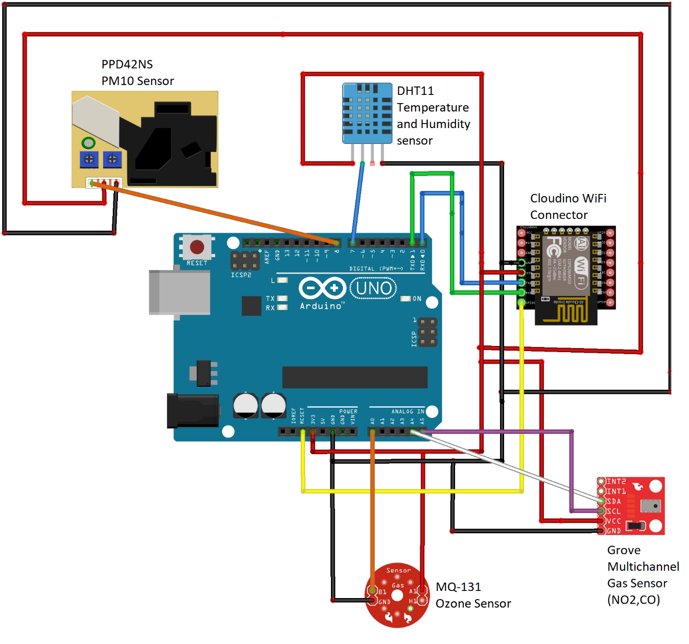 Fig. 1. Air monitoring unit diagram
The proposed schematic is intended for guidance/educational purposes and its components are easy to find; however, you can integrate any additional electronic components to your Arduino board to create more complex systems and post your measurements to both Cloudino and FIWARE platforms.
How to install and configure it
Create an application development environment at cloudino.io
In order to use the Cloudino Platform, it is necessary to access the cloudino.io portal which includes the tools that allows us to connect any device to IoT.
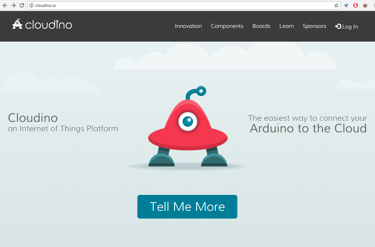 Fig. 2. Cloudino.io Portal
Firstly you need to create an account and login to the platform where you will find a configuration section to manage Cloudino devices, clouding rules and FIWARE Orion Context Broker (OCB) connections as well as a main Getting Started guide.
 Fig. 3. Login page
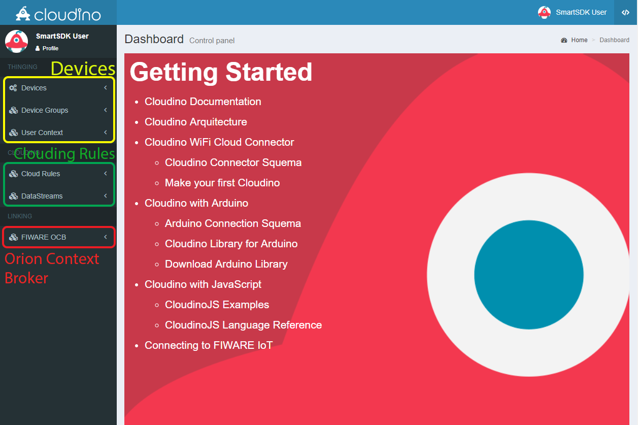 Fig. 4. Cloudino.io User's Main page
To connect your air quality sensor unit to the Cloudino platform, the Cloudino Wifi Connector needs to be set up in the portal. CWC is the hardware with Cloudino tecnology that allows you to connect any device to IoT.
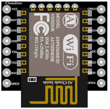 Fig. 5. Cloudino Wifi Connector
From the left side panel, select the Devices Menu and click the "Add Device" option. Then introduce a name, description and hardware type configuration; In this case, an Arduino UNO will be used for developing our air quality sensor unit as seen on Fig. 1. You must select the proper hardware type (Arduino) to use from the list or use Cloudino as standalone device. Click on the "Submit" button and our device will be created. You can register as many CWCs devices as you need.
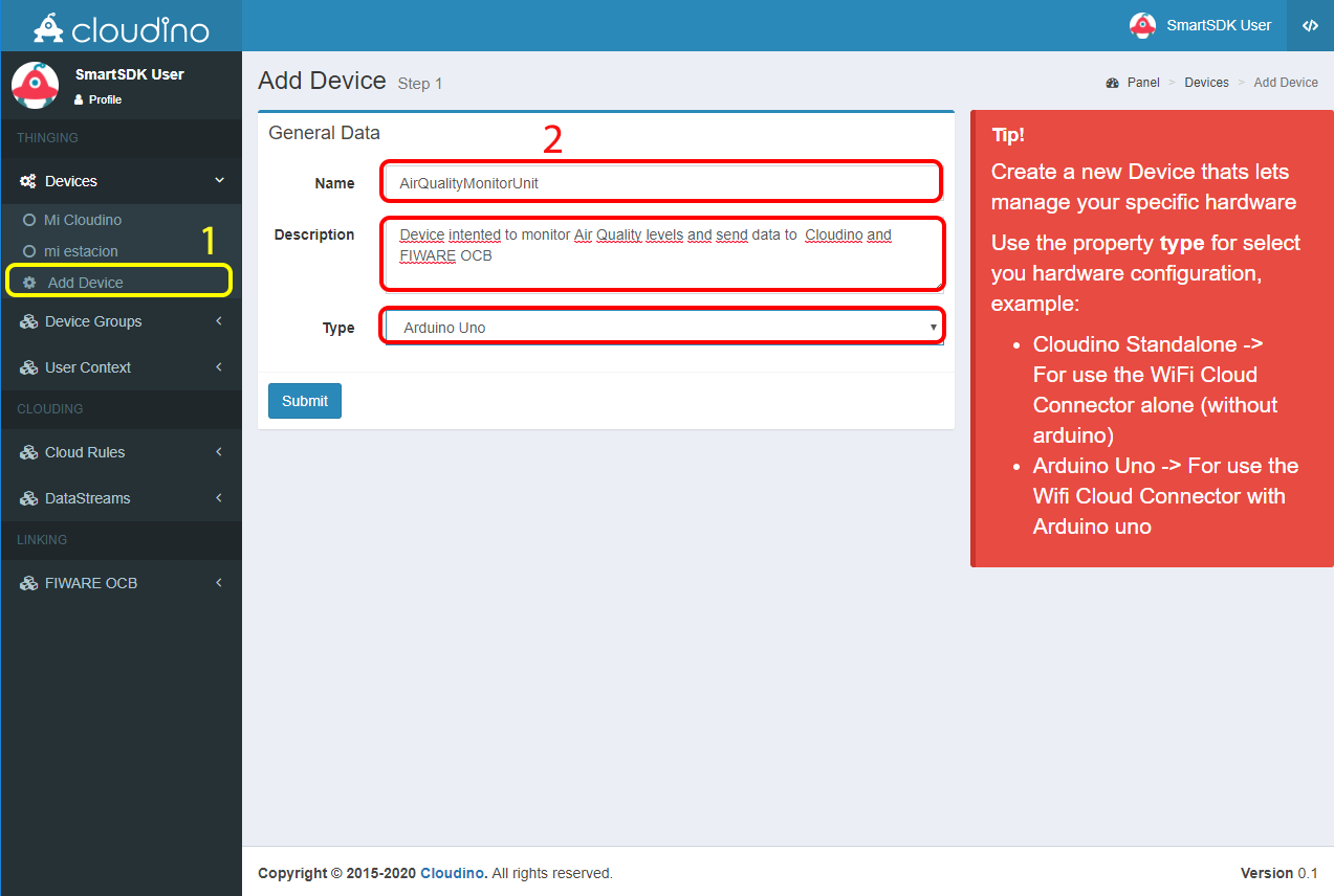 Fig. 6. CWC device registered
After creation, several sections will be shown in order to configure, control and program our device as seen on Fig. 8.
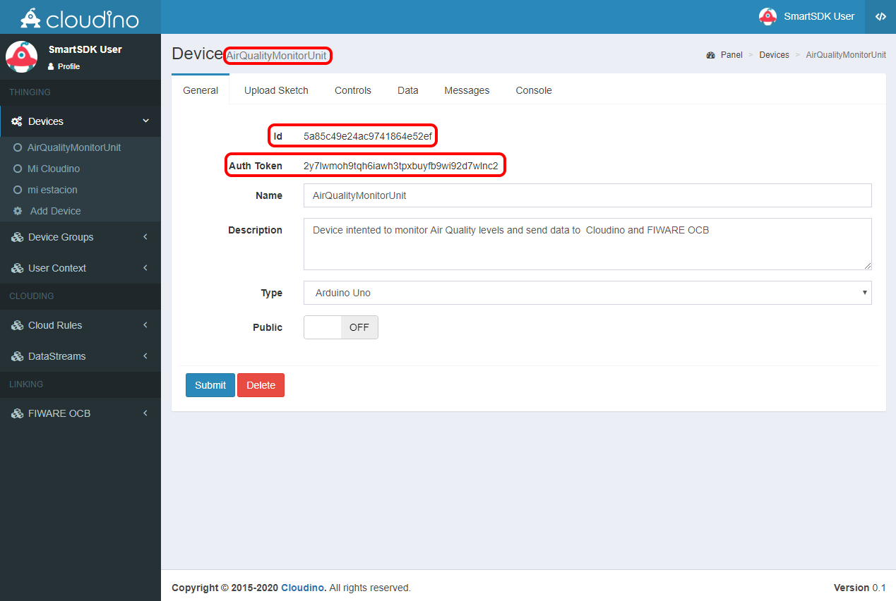 Fig. 7. CWC General Information
The General View shows the device's id, authentication token (Auth Token), name, description, type and security level (public or private). This information will be used later to associate our CWC to the device created in the portal.
Connect a Cloudino Wifi Connector to Cloudino.io Portal
Once you have created a device in the portal, it is necessary to associate the CWC to it by attaching the Auth Token generated in the previous step. In this way, our air quality unit will be connected to the Cloudino platform.
To perform this action, connect the CWC to a power source (5 volts). It will create a WiFi Network on which we need to connect to access the CWC configuration panel. The WiFi network's SSID is the serial number of the CWC device and is created without any password.
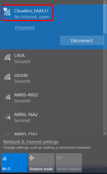 Fig. 8. WiFi network generated by any CWC
For instance, Fig. 8 highligths Cloudino_FAAE37 network that is used to configure the particular CWC (Cloudino_FAAE37 device).
As soon as the WiFi connection is made, a configuration panel shows up. In case it doesn't happen, you can access to the panel using a web browser with the 192.168.4.1 IP address. Fig. 9 shows the main configuration Web page for a CWC.
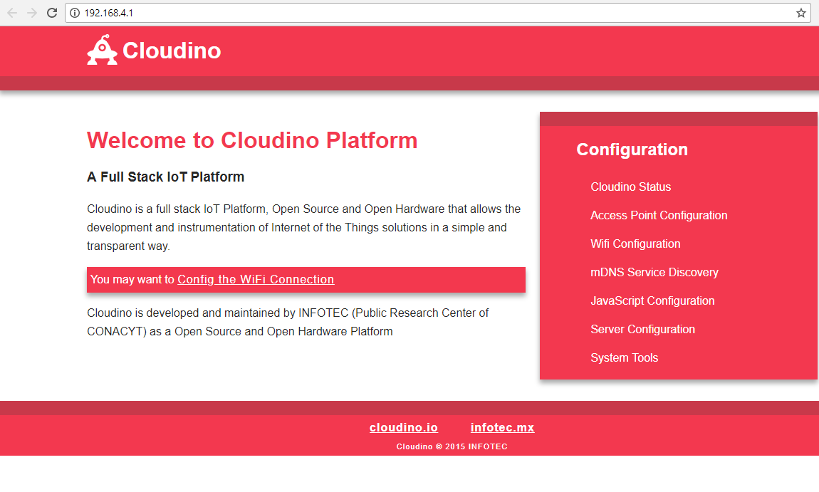 Fig. 9. CWC Configuration Panel on 192.168.4.1
The association is done by accessing "Cloudino Cloud Configuration" found at Server Configuration / Cloudino Server submenu. We need to copy/paste the Auth Token generated from the Cloudino Platform into the "Auth Token" field and switch the "Active" field to True, then click "Save" button as seen at Fig 10.
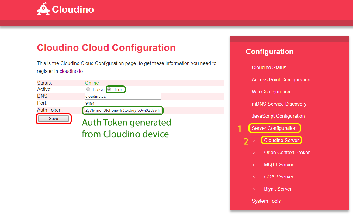 Fig. 10. Cloudino Cloud Configuration
Lastly, the CWC needs to be configured to access Internet over a WiFi network to be able to send data to the Cloudino Platform. Go to the WiFi Configuration menu, scan your available WiFi networks and connect to your chosen one. You can verify that the connection is correct when the "Status" changes to CONNECTED.
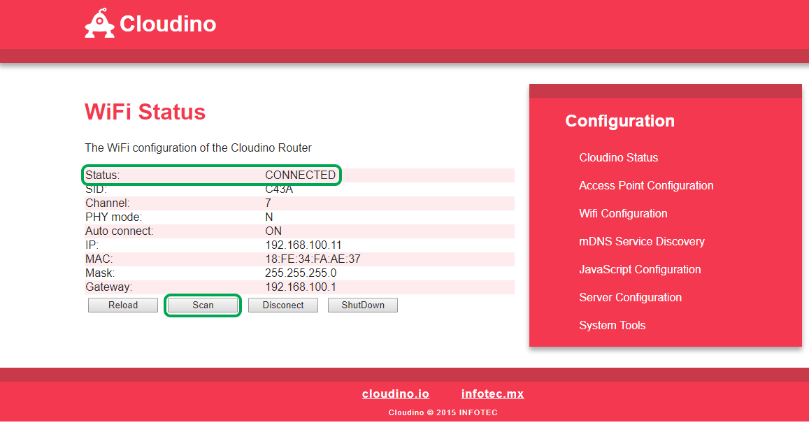 Fig. 11. WiFi Configuration Section.
The connection between your CWC and cloudino.io is established when the “Active” value is set to True in the Cloudino Cloud Configuration.
Verify connection between Cloudino Wifi Connector and Cloudino.io
To verify that your CWC is connected the Cloudino Platform you need to login again to the Cloudino Platform and go to "Devices" menu. If the connection is working properly you will see a green "online" legend aside your device created previously.
Be aware to properly disconnect your computer from the CWC WiFi and connect to an internet WiFi network
At this point your Cloudino/Arduino air quality sensor unit is ready to be programmed and controlled by means of the cloudino.io tools.
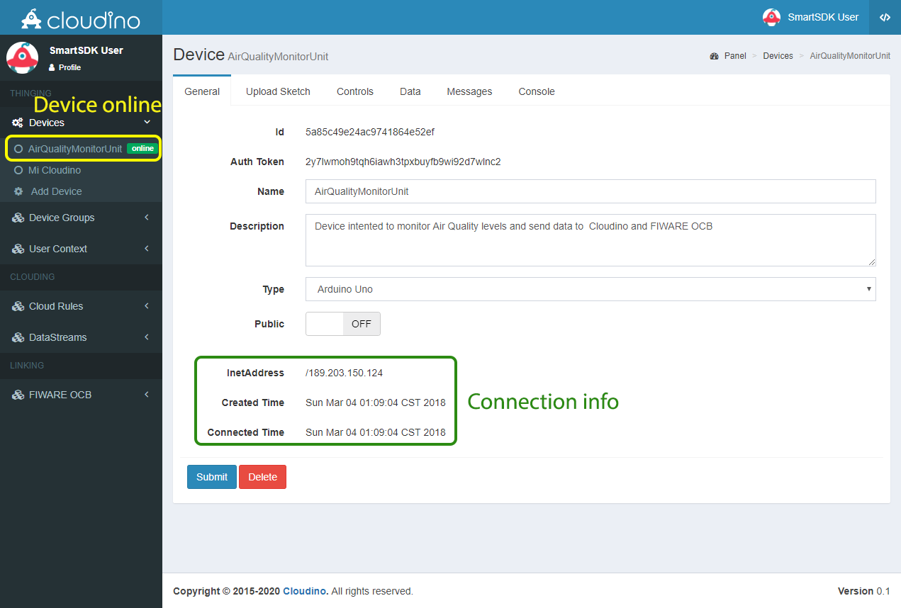 Fig. 12. Cloudino device online and ready to be used.
Define your application's logic through the development tools from cloudino.io
Once a CWC is registered in cloudino.io, we can proceed to program it along with the associated hardware "Arduino UNO" and sensors showed in Fig. 1. to define the behaviour of the IoT air quality monitoring application.
At first, we need to create a sketch –project- which has the same context and meaning of the Arduino technology. You must select the "Arduino" section from the dropdown menu indicated with icon and go to "Sketchers", where you can create or edit projects to be used on Arduino boards with the Cloudino technology. Select the "Add Sketcher" option as seen on Fig. 13.
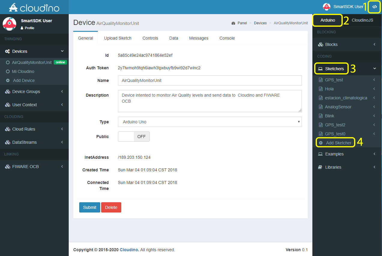 Fig. 13. Add Sketcher option in the Arduino menu
Then, you must enter a name for your Sketch (a program used to control an Arduino board), and press the "Submit" button, it will display a Sketcher area as shown in Figs. 14, 15.
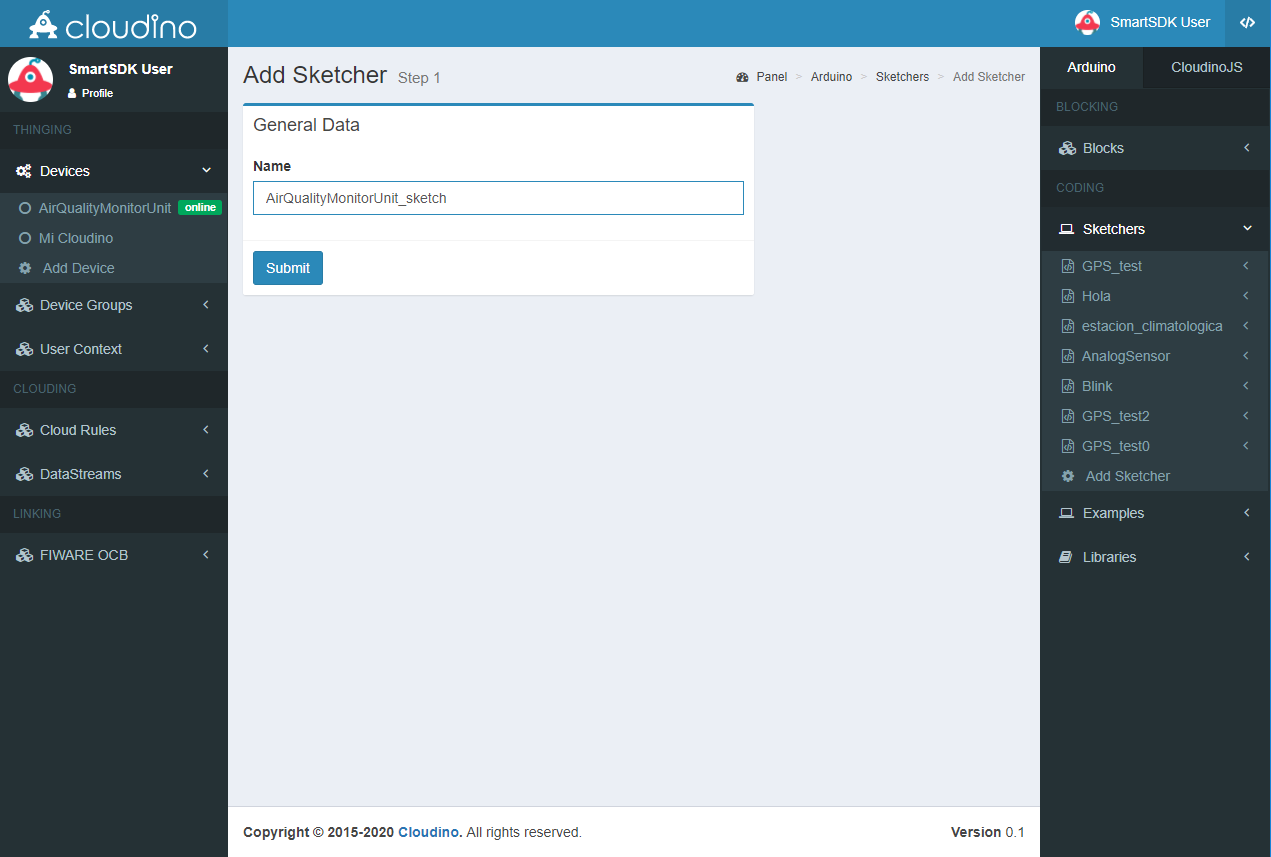 Fig. 14. Define the name of your sketcher
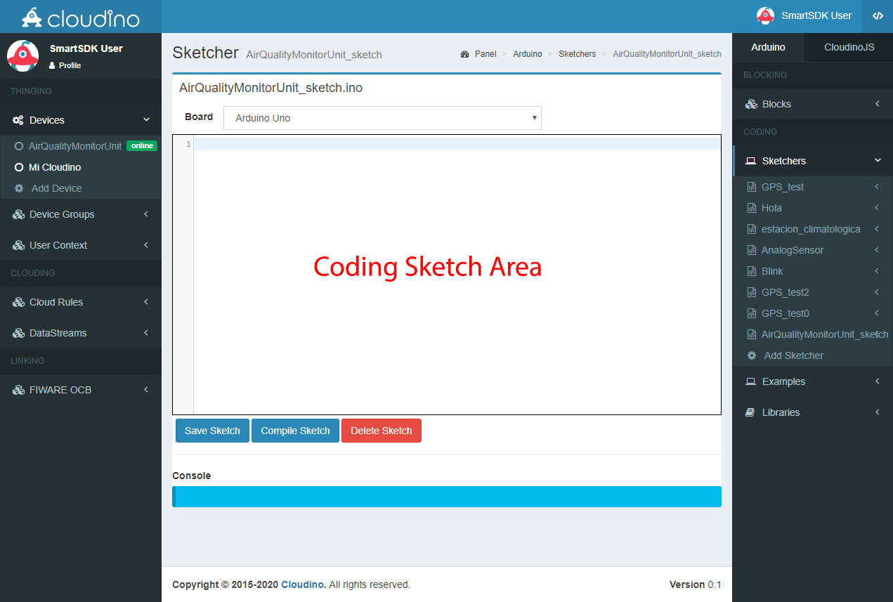 Fig. 15. Sketcher area: compile, save and delete your code
In Sketcher area, see Fig. 15, you can write the code to control Arduino, CWC and sensors for remote monitoring of your air quality unit. The code syntax is based on the Cloudino API (Application Programming Interface) which is a variant from Arduino, making it easier to be adopted by former and new arduino users. A broad description of the Cloudino API can be found at https://github.com/Cloudino/Cloudino-Doc.
Below we can see the arduino code to be used in the development of our air quality monitoring unit. It sends the raw values captured from the sensors showed in the diagram from Fig. 1 to the Cloudino platform using a post method.
#include <Cloudino.h>
#include <dht11.h>
#define DHT11PIN 7

Cloudino cdino;
dht11 DHT11;

const int analogPinO3 = A0;
const int analogPinCO = A3;
const int analogPinNO2 = A4;

void setup()
{
  cdino.setInterval(10000,getSensors);
  cdino.begin();
}

void getSensors()
{
   int chk = DHT11.read(DHT11PIN);
   cdino.post("temperature",String((float)DHT11.temperature,2));
   cdino.post("relativeHumidity",String((float)DHT11.humidity,2));
   cdino.post("O3",String(analogRead(analogPinO3)));
   cdino.post("CO",String(analogRead(analogPinCO)));
   cdino.post("NO2",String(analogRead(analogPinNO2)));
   cdino.post("PM10",String(digitalRead(8)));
}

void loop()
{
   cdino.loop();
}
The previous code captures the raw data from sensors except the DHT11 which makes use of its own library to calculate the correct temperature and relative humidity. To properly represent the measurements from many sensors, additional libraries might be needed
Once the code for the sketch has been written, it must be saved and compiled to verify that it is consistent with the Cloudino API, this process is performed by clicking the "Compile" button as shown in Fig. 16. The blue box (Console) shows the compilation status, here you can be aware of any compilation errors and success. To solve any compilation problems you should consult the Cloudino API on the Cloudino website.
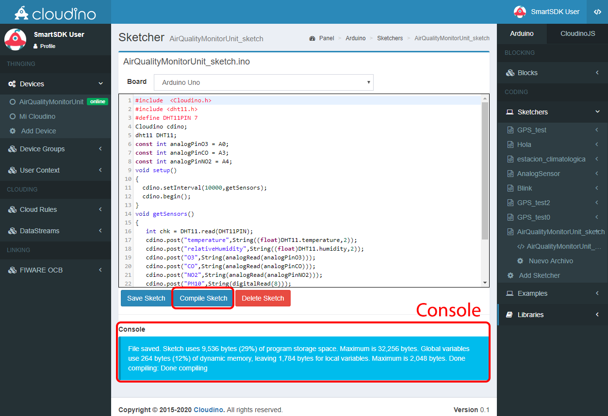 Fig 16. A sketch compiled with success
Now, the created sketch must be loaded to the actual device. This is done by using the "Upload Sketch" section within the selected device that is going to be configured.
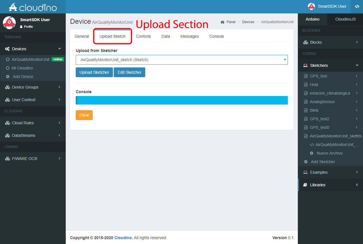 Fig. 17. “Upload Sketch” section from the selected device
A list of sketches developed by the user and samples is shown. We need to select the recently created sketch named "AirQualityMonitorUnit_sketch" and press the "Upload Sketcher" button in order to flash the compiled code in the CWC memory and the Arduino board to perform the developed functionality. The application logic is stored after flashing concludes succesfully Figures 18 and 19 show the process described above.
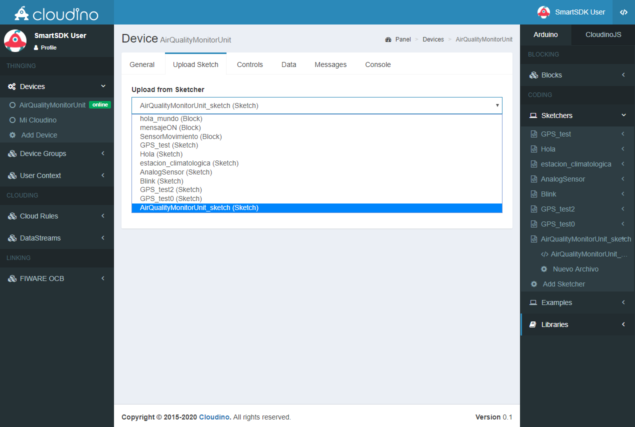 Fig. 18. Selecting a sketch for the device
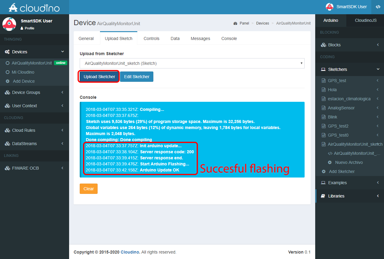 Fig. 19. Upload process of the sketch inside the CWC.
At this point, the functionality of the system according to the Fig. 1 is working. While the monitoring station is powered and connected to internet it will be able to send measurements to the cloudino.io server; with that said, data can be observed and used remotely. The developed code periodically sends the values reported by the sensors each second and displays them in the "Messages" section of the cloudino.io platform, as shown in Fig. 20. The console is updated in real time indefinitely while Cloudino is operating.
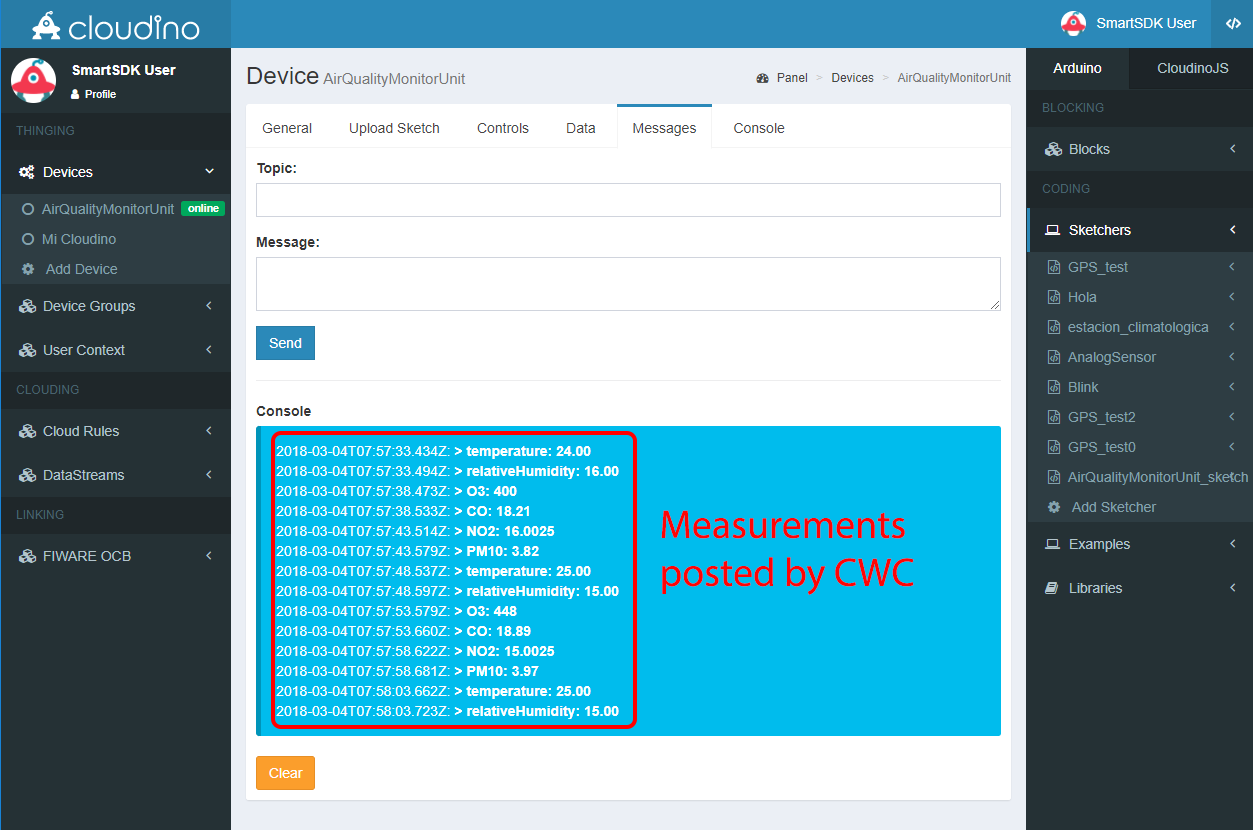 Fig. 20. Real-time measurements from your AirQuality monitoring unit
Your Cloudino as IoT Agent
The Cloudino itself operates as an IoT Agent able to work with FIWARE. Its Cloudino Platform lets us connect to the FIWARE Orion Context Broker following a simple series of steps.
To share the data of your developed air quality station in Cloudino with the FIWARE platform, you must first enter the "FIWARE OCB" menu and select the "Add Entity" option; this section helps you to define a link with the FIWARE platform. As shown on Fig. 21, it is neccesary to define a name for the link, a description and select a device (CWC) to be associated with the platform. In this manner, the data collected by Cloudino can be shared with the FIWARE platform.
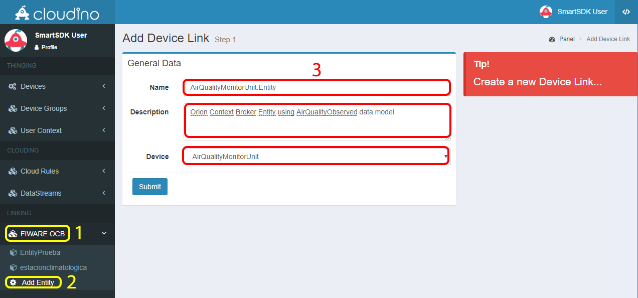 Fig. 21. Creating a link with the FIWARE platform
Once a link has been created, a configuration panel is displayed (Fig 22) where you can activate/deactivate the link, define the entity (data set) which will be shared in the FIWARE platform as well as the OCB server address that will be used to send the data and, when appropriate, the authentication data required to connect to the server. Fig. 22 shows the definition of the entity "AirQualityMonitorUnit:Entity" that includes all the data obtained from the previously developed air quality monitoring unit.
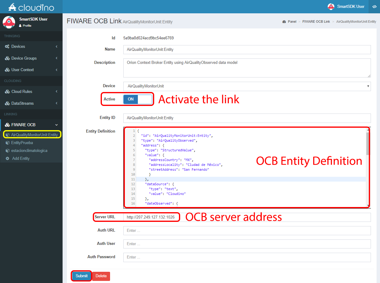 Fig. 22. Configuration panel of the FIWARE OCB Link and entity definition
The following JSON code describes the entity “AirQualityMonitorUnit:Entity” created in the previus step (Fig. 22):
{
  "id": "AirQualityMonitorUnit:Entity",
  "type": "AirQualityObserved",
  "address": {
    "type": "StructuredValue",
    "value": {
      "addressCountry": "MX",
      "addressLocality": "Ciudad de México",
      "streetAddress": "San Fernando"
      }
    },
    "dataSource": {
      "type": "text",
      "value": "Cloudino"
    },
    "dateObserved": {
      "type": "DateTime",
      "value": "2018-02-01T17:00:00-05:00"
    },
    "location": {
      "value": {
        "type": "Point",
        "coordinates": [-99.163309, 19.291001]
      },
      "type": "geo:json"
    },
    "temperature": {
      "type": "text",
      "value": "12.2"
    },
    "relativeHumidity": {
      "type": "text",
      "value": "0.54"
    },
    "O3": {
      "type": "number",
      "value": "1.6"
    },
    "CO": {
      "type": "number",
      "value": "1.7"
    },
    "NO2": {
      "type": "number",
      "value": "1.9"
    },
    "PM10": {
      "type": "number",
      "value": "3.5"
    }
  }
It is important to notice that the names of the variables used in cloudino must be equal to the names defined in the attributes of the FIWARE entity model.
After configuring the link, you must switch the "Active" option to "ON" and define the entity (previous JSON code) to be shared with FIWARE, then click the "Submit" button. It will automatically start to submit the data from the air quality monitoring unit to the FIWARE OCB.
To verify the operation, we can access the associated OCB server defined in the previous figure, i.e. http://207.249.127.132:1026/v2 without any authentication. In this way, Fig. 23. shows how the data defined in the entity and associated with the Cloudino is displayed and updated in real time on the FIWARE OCB server.
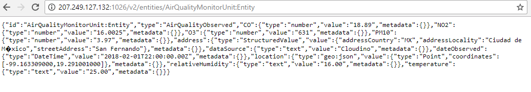 Fig. 23. Data of air quality monitoring unit in the FIWARe OCB
As can be seen on Fig. 23, the data of the air quality monitoring unit can be accessed with the following REST call: http://207.249.127.132:1026/v2/entities/AirQualityMonitorUnit:Entity,
where we can see the real time information of the air quality monitoring sensors controlled through the Cloudino platform. The information can now be used by any kind of IoT application.
Further details to developed your IoT applications with Cloudino and integrate with the FIWARE platform can be found here: https://github.com/Cloudino/Cloudino-Doc